|
|
 |
Read Chapter 6, but just skim sections 6.3 and 6.4. Then study this lesson. Complete hw 6. The topics in this lesson are important even though this is a short lesson. In this lesson we'll cover ASCII, asynchronous and synchronous transmissions, duplexing and terminating equipment. ASCII A simple equation used to determine the number of combinations given a specific number of bits (n) is shown below and solved for seven bits: L = 2n Hey, we only have 26 letters in the alphabet. Why do we need to use so many bits? Actually, we have both upper case and lower case letters, punctuation, and a bunch of control characters. It turns out all 128 unique bit combinations are used. Take a look at this ASCII table. It is used to find the seven binary bits that represent a character (or control character). Each character in a column has the same three bits, indicated at the top of the column. Those bits are actually bits numbered 7, 6, and 5. The characters in a row have the same final four bits indicated to the left of the row by bits 1, 2, 3 and 4.
For example, the letter E (upper case) is under the column with bits 100 (b7, b6 and b5). Add these bits to bits identified for the row that E is in (0101) and you get 1000101. Can you confirm that the following are true?
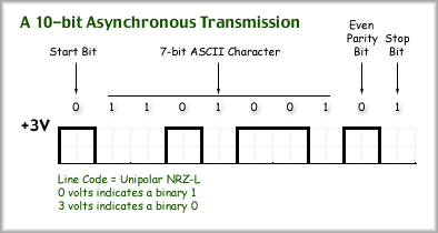
Example: Find an ASCII (or IRA) table on the internet and determine the binary values for the following: Then, check yourself with the answers provided. a) Space (SP) Answers: a) 0100000, b) 0001000, c) 0011011, d) 0100010 Some of the control characters shown are used by modems to establish and maintain connections. We will investigate how these might work in lesson six. Asynchronous and Synchronous Transmissions Asynchronous Transmission: A way of sending digital information in very small groups of bits with unknown amounts of time between each group. Synchronous Transmission: Sending digital information in large groups of bits with no break in transmission between groups. The key difference between the two is that synchronous transmissions continuously transmit information. If there is no information to send the transmitter will likely send zeros just to fill up the data stream. Asynchronous transmission will send some data and then stop. After an unknown period of time it will send data again. Asynchronous transmission uses start bits, stop bits, parity bits in addition to data bits. The start bit using a change in voltage indicates to the receiver that a data block follows immediately. After the start bit is a data block such as a 7-bit ASCII character. Following the data is a parity bit and finally a stop bit. The stop bit is usually zero volts.
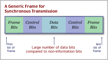
For the transmission of ASCII characters, the start bit indicates that a new character transmission follows immediately. The receiver uses the start bit as a reference point to set its measurement clock. Then the receiver measures the voltage of each bit (or symbol if 1 bit isn't equal to one symbol), hopefully in the center of the bit time. In other words, beginning with the start bit, the receiver uses its clock to time its measurements so that they land in the center of each bit time. As long as the receiver and the transmitter have the same value for a bit time, the receiver will always measure in the center of a pulse. A parity bit is included and used as a modest form of error checking. This bit is appended to the seven ASCII character bits and its value is set in a specific manner. Even Parity is a state where the number of marks, including only the ASCII character bits and the parity bit (8 bits), is even. By counting the number of marks (ones) in the ASCII character, a one or zero is added so that the the total number of marks will be even. In a similar manner, Odd Parity is a state where the total number of marks, including only the ASCII character bits and the parity bit, is odd. Again, a 0 or 1 is added at the end to bring the total number of marks to an odd number. Example: What would the parity bit be for the following 7-bit ASCII characters, if the system uses odd parity? a) 1011010 Answer: a) 1; b) 0; c) 1 A stop bit concludes the short transmission. If another data block does not immediately follow, then the value of the stop bit is repeated as long as necessary. The repeated bits are called idle bits. The receiver resets its clock each time a start bit arrives and then uses its own clock to determine when to measure each bit. Usually only one character is sent at a time. Including the start bit, stop bit and parity bit, this adds up to 10 bits for an ASCII character. Unfortunately, only 7 of the 10 bits are actually information we wanted to transfer. We can define a new term here. Overhead is the fraction or percentage of non-information bits in a transmission. non-info bits So, given 3 non-info bits and 10 total bits, we have 30% overhead in the ASCII transmission system described above. Example: What would the overhead be for a character transmission that uses one start bit, a 7-bit ASCII character, one parity bit and two stop bits? non-info bits 4 If 36% is overhead what about the remaining 64%? Of course, that is the actual information transfer, which we'll call "through put". info bits 100% = overhead + throughput Example: A 16-bit unicode character is transmitted asynchronously with one start bit, one parity bit and 3 stop bits. What is the overhead and through put? non-info bits 5 Throughput = 100% - overhead = 100 - 23 = 77% The advantages of using an asynchronous transmission is that the receiver must only maintain accurate timing for a short period, just long enough to measure all the bits of a single transmission. This translates into inexpensive equipment. One example being a modem. The disadvantage, which you saw above, is that there is a large overhead. Synchronous transmission takes a large block of information bits and places a fixed sequence of bits at the beginning and end to identify them. Control bits are added as well. Together, the total collection is called a frame.
The bits at the beginning, identifying the start of the frame, are called either frame bits or flag bits. An identical set of bits are used to mark the end of the frame. Frames are sent consecutively, without a break, on a synchronous transmission line. A T1 is an example of a synchronous transmission line. It sends bits without stopping. If there is no information to send, it sends zeros to keep the line up and running. One advantage of synchronous transmission is that a very large block of information bits can be transmitted as a single block. The result is low overhead. Example: What is the overhead and through put for a synchronous system that uses 1000 bit frames containing 968 bits of user information? info bits overhead = 100% - throughput = 3.2% Another example: How many bits can be used for control and framing if a minimum through put of 90% is required and the frame size is 1500 bytes (8 bits = 1 byte)? overhead = 100% - through put = 100 - 90 = 10% overhead bits overhead bits 10 x 1500 x 8 Yet another example: What is the total bit rate, the overhead bit rate and the information bit rate if 8000 frames are sent per second, the overhead is 5.18135% and there are 193 bits in a frame? total bit rate = 193 bits/frame x 8000 frames/sec = 1,544,000 bps overhead bit rate = 5.13185% x 1,544,000 bps = 80,000 bps information bit rate = 1,544,000 - 80,000 = 1,464,000 bps Another advantage of synchronous transmission is that variable sized frames can be sent. The receiver watches for the frame bit sequence to locate the end of the frame. This can be at any time and can change on a frame by frame basis. For example, if the framing bits at the beginning and the end of the frame are 01111110, then the receiver looks for this sequence to determine the end of the frame. The main disadvantage here is that accurate timing must be maintained for extended periods of time, resulting in costly equipment. Providing timing over extended periods of time can be done in these two ways. One is to provide a separate clocking lead. This is a dedicated wire pair that carries a constant clocking signal (as discussed in an earlier lesson). The second method to provide timing information is to use a line code that has frequent voltage transitions. The receiver can use the voltage transitions to keep track of bit intervals. For example, Manchester line coding provides at least one transition for every bit sent. This offers the receiver all the information it needs to properly time its measurements.
Duplexing Simplex describes a one-way transmission. There really is no communications as there can be no response. Half Duplex describes two-way communication on a shared medium. Because the medium is shared, the transmitters have to communicate by taking turns. That is, only one end may transmit at a time. Full Duplex describes two-way communications where the transmissions in both directions may occur simultaneously. A good analogy might be as follows: Simplex is like a one-way street, full duplex is like a two-lane two-way road, and half duplex is like a one-lane bridge on a two-way road. For most applications it is our desire to provide full duplex channels. How might this be done? The easiest way is to provide separate wire pairs, one pair for transmission and the other pair for receive. This may be called Space Division Duplexing, SDD, but it is so common that no one really feels the need to express it as such. Frequency Division Duplexing (FDD) Time Division Duplexing (TDD) DTE versus DCE A DTE is a source or destination on a network, such as a printer, computer or scanner. A DTE usually uses a very basic or simple line code, such as NRZ, to transmit data over short distances, but a high through put. A DCE provides the DTE translation services and access to long distance transmission media. The DCE handles any data conversion that needs to be done (a translator) in either direction. Yet, the distinction between these devices is blurring. Not long ago, computers connected to the Internet through an attached external modem. A modem is a DCE that provides access over long distances (phone lines) to another DCE at your ISP. Now that the modem is nearly always built in, is it still a DCE? As an external item, it fits the description perfectly. As an internal item it still provides the same functionality. We will still call it a DCE. Some of you may be familiar with routers, the boxes at the intersections of the Internet that make decisions about which direction to send information that is traversing the information highway. Routers connect to each other with a DTE to DCE relationship. Usually, the upstream service provider's router is the DCE and, for example, your router is the DTE. This is important because usually, the DCE provides that clocking signal we keep talking about. Only one router is to provide the signal and communications will fail if the wrong instructions are given to either router. |
| [INF 680 Syllabus] [How to Start] [Schedule] |
Used with permission of the Author; Copyright (C) Kevin A. Shaffer 1998 - 2018, all rights reserved. |


