|
|
 |
Read Chapter 12 in your text and this lesson. Then, complete hw 12. This lesson discusses Ethernet and Token Ring local area networks. At first, we will look into the operation of Ethernet. Later, we will discuss the various Ethernet stages of development. After that we will investigate Token Ring networks. Ethernet Overview Robert Metcalfe's The original concept was
that Ethernet was a broadcast environment. All stations on the network would see all frames. Addresses would be included in the frames so that each individual station could determine if the frame was
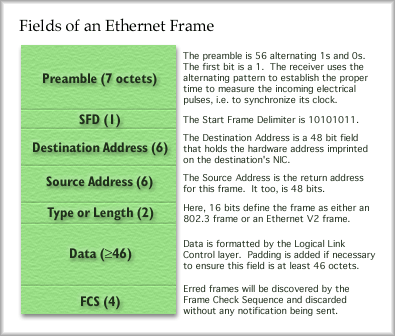
destined for itself or some other station. Ethernet Framing When the receiver sees the last bit of the eighth octet, which does not follow the one-zero pattern, it knows the immediately following field is the Destination Address. The destination address is 6 octets, or 48 bits. When you buy an Ethernet Network Interface Card (NIC), a unique address has already been imprinted into the cards memory. You cannot change the address on the card. To change a computer's NIC address, you will need to change the card.
Ethernet addresses are usually written in base 16 with colons separating each octet of bits. The first half of the address, 24 bits, defines the vendor. Cisco's vendor code is 00:00:0C. The card manufacturer would then assign a unique number for the remaining 24 bits on the card. So, for example, 3Com might produce a card with the following Ethernet address on it: 00:60:8C:01:02:05. This is much easier to write than a string of 48 bits. An alternative way to write the address is three groups of four digits with a dote between the groups. This is somewhat similar to an IP address. An Ethernet card manufactured by Cisco might have the address 0000.0c00.1234. Please note that this address is only valid on the Local Area Network and only valid at layer two of the OSI model. An addressing scheme at layer three provides "inter-network" connectivity, such as Appletalk, IPX or IP. Card vendors have to purchase blocks of address space for their use from IEEE. They are not supposed to reuse any address, but it happens. If two cards on the same network have the same address, there will be noticeable problems for both of these end stations. Properly manufactured cards of different vendors should work together flawlessly on an Ethernet network, provided the cards are for the same Ethernet standard, which we'll discuss later. A Source Address is included just after the destination address. It is 48 bits long, of course. If any reply is expected, you'll certainly want to include your return address. After the address fields is the Type/Length field. As Stallings' notes, the IEEE 802.3 Ethernet standard uses the next two octets as a length field. If this field contains 0000 up to 05DC, then the field is an 802.3 standard frame and the number defines the length of the frame, from 0 to 1500 bytes (05DC in base 16 is 1500 in base 10). Values from 05DD up to FFFF are used to define the type of data in an Ethernet Version 2 frame (versions explained later). For example: 0800 would indicate an IP datagram Following the Type/Length field is the payload, the data field. The contents of this field do not come from layer 3, however. IEEE 802.3 is a standard that defines the MAC sublayer and the Physical Layer. The data field is actually assembled by the LLC sublayer. The IEEE hasn't missed its chance to create a standard for the LLC sublayer here. They've defined IEEE 802.2 to establish how the LLC functions and the format of the LLC data. The data field must be at least 46 octets. If there isn't enough data to fill this, the LLC sublayer will fill in the remainder with padding, a bunch of dummy bits that take up space but get ignored on the receive end. The last field of an Ethernet frame is the Frame Check Sequence . This is a large field for an FCS, being 32 bits long. The FCS checks the fields between the Start Frame Delimiter field and the FCS field. Like Frame Relay, the receiver will check for errors and discard the frame if any are found. No notifications are sent that a frame was discarded. It's up to the higher layers to figure this out on their own. The method used to check for errors is a Cyclic Redundancy Check, or CRC. The complete frame has a fixed size range. An Ethernet frame must be at least 64 bytes long but no more than 1,526 bytes long. Ethernet Media Access In a nutshell, Ethernet tries in a mild way to avoid this problem. Before an end station can transmit on the medium, it must listen to see if the medium is in use. If the station hears a carrier signal, it must wait and try again later. If the medium appears free the the station sends the frame and then listens to see if a collision occurred. This process is called Carrier Sense Multiple Access Collision Detect. Uh oh, another acronym: CSMA/CD. Let's dissect this acronym more carefully. Multiple Access (MA): Ethernet is a broadcast media that permits multiple stations to compete for the exclusive use of the medium. Only one user may transmit at a time. Carrier Sense (CS): Stations listen before transmitting to see if there is already a carrier signal on the line. If there is no carrier, the station sends its frame. If a carrier (a signal) is present, the stations waits until the carrier clears, waits an additional 9.6 micro seconds (9.6 x 10⁻⁶ sec), and then transmits. Collision Detect (CD): If more than one station transmits at the same time a collision occurs.
Because transmitters stop immediately when a collision is detected, fragments of the frames that are less than 64 bytes long will propagate through the network. These are called collision fragments. The worst case for a collision is two stations at opposite ends of the media. One end station transmits and the frame propagates to the other end of the media. Just as the first bit of the frame arrives, the other end station begins transmitting. A collision occurs at the instant and the second end station stops transmission and sends a jam signal. The first end station will receive the collision fragment and jam signal. What happens after two transmissions collide? After detecting a collision, a station knows it must transmit its frame again. Before doing so, the station will execute a "backoff" algorithm. The backoff algorithm determines how long the station will wait before attempting to transmit again. Backoff Algorithm: The station determines a random number. The number ranges from 0 to K. K is equal to 2n - 1, where n is the number of consecutive collisions.
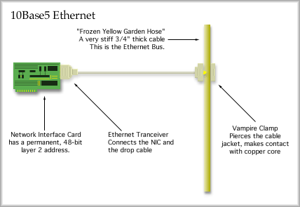
If a second collision occurs, n would equal 2 and a random number would be determined. The random number is multiplied by 51.5 micro seconds to find the amount of time to wait before attempting to transmit again. The minimum wait is zero seconds and the maximum wait is 0.0526845 seconds. The same random number range is used for 10 to 15 collisions. If more than 15 collisions occur, a notice to the upper layers is sent saying the medium is not accessible. You'll get a window that says something like, "... an error occurred while trying to connect to ..." Ethernet Designations IEEE created a scheme to identify various versions of Ethernet. Thicknet was assigned the following: 10Base5 The 10 represents the transmission rate in megabits per second. "Base" stands for base band, which means that no multiplexing is taking place. Your transmission gets the full bandwidth the full time. The last character, the 5 in this case, represents the maximum distance of the medium in hundreds of meters. The maximum is 500 meters for Thicknet. Other designations following this pattern include 10Base2 and 10Base-T. The T stands for twisted pair. OK, IEEE didn't follow their own scheme for very long, did they. You may also encounter 10Broad36, 100Base-T, 100Base-F (F for Fiber) and 1000Base-T (or F). 10BASE5 Ethernet The maximum length of the bus was 500 meters. The "frozen yellow garden hoze" was marked every 2.5 meters with a small black ring. At that location a 'vampire' clamp was attached. From the clamp, a wire ran to a transceiver and then on to the end station. The vampire clamp looked like a small jaw with a copper spike in it or a sandwich shaped clamp. The spike pierced the thick jacket on the cable and made contact with the copper core.
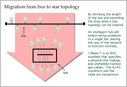
Thicknet, Ethernet V1, was adopted as standard IEEE 802.3 in 1983. In 1984 ANSI formalized a standard and in 1985, ISO adopted it as well. You are not likely to be installing this because it is obsolete, but you may encounter it in the field. 10Base5 supports up to 100 attached transceivers and uses 50 ohm coaxial cable with a solid center conductor. Each end of the bus must be terminated with a 50 ohm terminator. Without terminators, the signal will reflect and travel back down the cable. If the cable should be cut or shorted, reflections will occur. This means that a wire fault takes down the entire network. 10BASE2 Ethernet Only 30 stations can be connected to the bus at a time. However, stations only need to be half a meter apart. While the designation indicates a 200 meter bus, the actual limit is 185 meters. Hey, who would want to call it 10Base1.85? 10Base2 uses RG-58 coax. This is 50 ohm coaxial cable that looks just like cable TV cable. Unfortunately, cable TV cable is 75 ohm RG-59 coax and won't work right for this version of Ethernet. This is version 2, by the way. Thinnet is still fairly popular, but it is a troubleshooting nightmare. A single malfunction in the bus causes the whole network to malfunction. A poor terminator, a bad T-connector at the workstation or a wiring fault all cause a similar problem, the network fails. 10BASE-T Ethernet By shrinking the length of the bus, enclosing it in a small box and then extending the length of the drop cables a star network results. Putting some intelligence in the central box, or hub, allows a wiring fault or other problem to be isolated from the rest of the network.
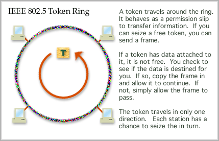
10Base-T has become popular because it is inexpensive and fault tolerant. Twisted pair Ethernet was standardized in 1990. The standard specifies a physical star with 100 meter maximum links from hub to workstation. It runs at 10 Mbps over Category 5 cable, using only two of the four pairs. A link status monitor continuously checks the link. If there is a problem, the hub will shut down the link to isolate the fault from the rest of the network. Hubbed Ethernet is giving way to switched Ethernet. A hub, as you learned earlier operates at layer one as a multiport repeater. An incoming signal is sent out all other links. A switch, however, can replace a hub and improve the network operation. Intelligence in the switch allows it to review the layer two address and choose the proper outgoing link for the Ethernet frame. When all stations are attached to a switch, simultaneous communications can occur without collision. Thus a major improvement in capacity for a group of users can be realized by changing from a hub to a switch. The best part of this upgrade is that NICs do not have to be changed. Consider the cost of replacing al 1000 NICs at FHSU at $100.00 each. Hmm, just the hardware will be $100,000. Now compare that with the cost of replacing fifty hubs with fifty 10 Mbps switches at $500 each. That's only $25,000 and the labor will be significantly less. Other Ethernet Standards Gigabit Ethernet, or 1000Base-T is becoming very popular for Ethernet backbone links on fiber. It will become popular for desktop and laptop computers fairly soon. The standard specifies using common category 5 UTP. All four pairs are used to support this transmission. Unfortunately, many installers used to attach RJ-45 clips but only terminate two of the four wire pairs, leaving no upgrade path on that "expensive" wire the architect specified (expensive because installation costs so much, not the wire). Too bad, all those terminations have to be redone. Recently, most organizations with forethought pull both category 5 and optical fiber at the same time, install switched 100 Mbps Ethernet to the desktop, with 1000 Mbps Ethernet to servers and 1000 Mbps on the backbone. There is a very small additional cost to purchase and pull fiber if you are already paying installers to pull Cat 5 cable. The labor is the major cost, not the materials. The most recent addition to the ethernet series is 10Gig Ethernet. PC cards and networking device interface cards supporting 10GigE are available on the market now. Note that the backplane of most PCs will not support interchange with such a card at that high of a data rate. However, 10GigE can be used to aggregate multiple gigabit Ethernet links together onto one core backbone link. Fiber is the prefered media to carry 10Gig Ethernet. Token Ring and FDDI When a station is ready to send a frame it will seize an available token and attach data to it, fill in some addressing info and send out the frame. This frame will travel around the ring and each station will look at it in turn. When the token passes the destination station, the frame is copied in as it passes. The token will continue around the ring until it returns to the sender, where it is absorbed. The sending station must build a new available token (or simply rebuild the old one) and release that on to the ring. The next station down the line will have the next opportunity to seize the token. In this manner each station will be able to send a frame in turn. Token Ring is standardized as IEEE 802.5. It can operate at 4 Mbps or 16 Mbps. The 4 Mbps is almost as efficient as 10 Mbps Ethernet, but it is also just as old. Unfortunately, Token Ring hardware tends to be expensive and it has fallen out of favor. The cabling is more difficult to work with and additional administration is required. With Token Ring, up to 250 repeaters can be used in series on STP cable. Using 4 Mbps Token Ring and UTP, up to 72 repeaters can be linked in series. This means that a Token Ring can cover a lager geographical area than Ethernet.
Token Ring, running on UTP or STP uses Differential Manchester Encoding. A differential code usually implies that a 0-bit is encoded in the same manner as the preceding bit. A 1-bit is encoded the opposite of the preceding bit. For Differential Manchester, you would have transitions in the middle of every pulse. Zeros would also have a transition at the beginning of the pulse. Fiber Distributed Data Interface, or FDDI, is a physical ring topology taking advantage of fiber technologies. A double ring provides transmissions in both directions simultaneously and also provides for redundancy. The ring operates at 100 Mbps. Unlike Ethernet, a Token Ring network can achieve much greater efficiency under heavy load. There are no collisions with Token Ring and that is the reason that it is much more efficient under heavy load. Token Ring has two interesting features that are not available in Ethernet, Reservation and Priority . These two features work in concert with each other. An administrator would set up a priority level for each machine. Token Ring offers 8 priority levels. The highest priority level would be 7 and the lowest would be 0. For example, as an administrator, I would set my work station to level 7, the students to 6, the staff to 5 and the upper administration here on campus to 3. How would this work? Well, tokens are marked with a priority level. If the priority level of a free token is equal or lower than my own priority, then I may seize the token. If not, I can try to reserve the token. If the reservation level of the token is equal to or less than my priority level, then I may make a reservation. To do that I mark the reservation field with my priority level. Ah, you now see that when ever I have a frame to send, I'll gain access to the token rather quickly and the administration will have to wait. OK, so let's say I'm finished sending frames and release a token. I set the reservation level back at the level it was at when I seized it. Any station that raised the priority level is responsible for setting it back to the level is was originally at when it seized the token. In this manner, the reservation level of the token slowly works its way back down to level three, where the administration can finally gain access to the token. What's the net effect? Students and Staff are reasonably satisfied with network performance. The administrator is happy (very important) and well, the administration sees poor network performance (artificially low). The administration finally concedes to provide more money to increase the campus networking capacity. Being the network administrator does have its advantages. ;-) FDDI , unlike 802.5 attaches the token to the end of a frame (or multiple frames). This permits a free token to be released immediately. This allows nodes to seize the token much earlier than in the standard Token Ring protocol. In a physical ring topology, media problems bring the whole network down. So, attempts were made to create a hubbed token ring architecture. This proved successful, but the cabling can be expensive. By pulling the free sides of the ring inside a box, a physical star can be created. Tokens still circulate from one station to the next in order by traveling out to a node and then back to the hub, visiting each station in a round robin fashion. If a link fails, the hub will isolate that link. Attempts to create a switched token ring architecture have also been made. A physical star topology radiating from a central management hub. Each node would be offered its own exclusive token, which simply traveled back and forth. It turns out this didn't make much of an improvement over standard Token Ring.
|
| [INF 680 Syllabus] [How to Start] [Schedule] |
Used with permission of the Author; Copyright (C) Kevin A. Shaffer 1998 - 2018, all rights reserved. |