|
|
 |
Read Chapter 5 in your text and study this lesson. Complete hw 5. Digital and analog transmissions of digital and analog information. The bulk of communications is moving toward digital transmission of signals on copper and fiber media. In this lesson we'll look at the ways digital and analog signals are converted to more convenient forms and how improvements can be made to some of these systems. Let's layout the ground work by organizing our options.
We will discuss the last three rows of the table above. If you are interested in AM and FM, you might take Point-to-point Transmission Systems next fall. Another route would be Radio and Cellular Systems in the Spring. These courses will dig a bit deeper into how they work. The last row, digital info carried on digital signals is quite popular these days, now that the Internet is such a pervasive force. We'll spend nearly all the remaining time in this course working under the assumption that we are on pure digital systems for data communications. In this lesson your task is to learn methods of sending analog signals and digital signals across media and how to convert from one form to another in preparation for transmission on media.
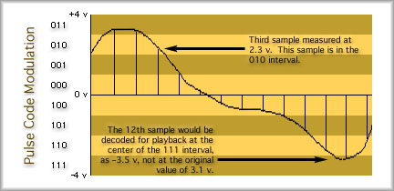
Converting from analog to digital The compression waves travel through the air to the microphone which converts the compressions into an analog electrical current that varies up and down in synch with your voice. The computer will take that signal and convert your voice signal into bits using a digitizer. The bit stream is stored in memory for later use (or sent out immediately in the case of chat). One popular way of doing this is called Pulse Code Modulation, or PCM. Here is how it is done. Your voice is measured once every 0.000125 seconds, or 8000 times per second. The digitizer looks at the voltage that comes in from the microphone to determine the amplitude (voltage) of the signal. The digitizer then assigns a combination of bits to represent that sample. How does the digitizer know what bits to assign? The digitizer simply divides the total range of possible voltages up into small intervals. It then labels each interval with a unique combination of bits. An extremely simple version is shown below. The range from -4 V to +4 V is divided into 8 intervals, each 1 volt in size. The eight intervals can be uniquely identified with just three bits. Each sample is simply assigned the bit combination for the interval that it falls into.
Once the bits are determined, they can be sent out just as any other digital information would transmitted. When the signal is reproduced on for the listeners in the chat room, for example, the signal value is decoded from bits to a voltage again. The only issue here is that we don't know what the original value was. We only know what interval it was in. For this reason we reproduce a voltage that is in the center of the interval. This means we have some error. You may think of this as a round off error, but it is usually called "quantization error". When we reproduce the voice it will be a very close approximation of the original. To improve our quality we can double the number of intervals. That means our error will be half as big. Double again and our gets smaller still. Obviously the more levels we have the better the quality. As the number of intervals, called levels, increases we have to use more bits to uniquely identify them. With three bits we had eight levels. With 4 bits we would double that number of intervals and as a result our intervals would be half as big. How many would we have? L = 2n Where L is the number of unique combinations we can make with a given number of bits, and 'n' is the number of bits we need to do that. L = 24 Example: Voice signals need about 13 bits to identify enough unique intervals for good voice quality. a) How many intervals would that require? L = 2n b) If we expect the maximum voltage of the signal could be +3.0 volts, and the minimum voltage could be -3.0 volts, how large would one interval be? range = 3V - (-3V) = 6 volts The range is divided up into 8,192 levels, so one level would be: interval = 6V / 8,192 = 0.000732 volts The PCM (pulse code modulation) digitization process described above is a linear system. This means that all the intervals are the same size. There is a more advanced type of voice digitization called u255 Companded PCM. Companded means 'compressed and expanded' and u255 Companded PCM encoding is often called 'u-law' for short. u255 uses smaller and smaller intervals as the voltage approaches zero. That way the error will not be very large compared to the value of the signal. Linear encoding uses 13 bits per voice sample and u255 uses 8 bits per sample. What are the advantages of this? Look into the next example. Example: What is the data rate for voice using linear and companded encoding if we must send 8000 samples per second to maintain good quality voice reproduction? R = r x n Where R is the data rate (we've seen this eqn. before), R = 8000 samples/sec x 8 bits/sample R = 8000 samples/sec x 13 bits/sample From the example you should be able to see that we don't need as much bandwidth to send quality voice communications over digital transmission systems if we digitize the voice with companded encoding. Digital Data on Analog Channels We studied sine waves in an earlier lesson. Now let's take advantage of that knowledge. Combining a high frequency radio wave, a carrier, with the digital signal we can send digital information over an analog channel. Here are two signals, the carrier wave and the digital information.
By multiplying the value of the carrier wave with the value of the bit stream, we get a 'modulated' carrier wave. A carrier that contains the intelligence of the original bit stream but one that can travel over the airwaves. Here is what we get.
At the far end of the medium, the receiver is listening to determine if a one or zero was intended. If the signal has not degraded too much, the ones and zeros can be determined exactly. The above system is a very simple way of sending digital information over an analog channel. This particular method is known as Amplitude Shift Keying, or ASK. As shown above, only one bit is represented by a single signal. We could use four amplitudes (four unique symbols) and indicate two bits with the transmission of a single signal. That would double our data rate. Two other methods are also popular. FSK, or Frequency Shift Keying, uses two different frequencies to indicate ones and zeros, for example. Four frequencies would permit us to send two bits per symbol. PSK, or Phase Shift Keying, uses two different phases. FSK
Before we take a look at PSK, let's consider what phase is. A sine wave usually starts at zero and heads upwards toward its first peak. However, if we change the phase, by adding in some extra value to the angle like this, sin(2pi f t + x), we can offset this zero point. Adding 180 degrees (or pi radians) allows us to move the sine wave enough that it begins at zero but starts out moving down. Using these two different signals allows us to send binary ones and zeros, just as we did with FSK and ASK. Take a look.
Summary: FSK = Frequency Shift Keying. Change the frequency of the carrier wave to indicate each unique signal. PSK = Phase Shift Keying. Change the phase of the carrier wave to indicate each unique signal. Each of the methods above can send one bit per signal or more (subject to the signal to noise ratio limit we studied in lesson three of course). They can also be combined. See if you can guess what the following is:
Looking at the signal there seem to be phase changes and amplitude changes. The frequency remains the same. This is an example of ASK combined with PSK. Two bits can be sent with each signal. A very popular technique is QPSK, which means Quadrature Phase Shift Keying, where four phases are used. This means that two bits are indicated by a single signal transmission. Digital Information Sent as Digital Signals Unipolar NRZ Line Coding bit time = b = 1/R Where R is the data rate in bits per second and b is the bit time in seconds per bit. b will be a very small fraction if the bit rate is high. Here is what this might look like.
In the example shown, the bit time is one second. That would give us a data rate of: b = 1 / R Maybe we should shrink the bit time a little. :) One problem with unipolar NRZ (and all unipolar line codes) is that there is a net flow of electrical current from one end to the other. Current is either positive or zero.
Bipolar NRZ Line Coding
If we have close to the same number of ones and zeros, then the average current flow will be zero. This means we'll save some power when we run the system. For short distances, like those within your computer from CPU to hard drive, this isn't really an issue, but for long distances, it can become very important. For longer distances, slightly more sophisticated line codes have been developed. AMI Line Code for T-1 Transmissions
Let's make a rule that when you don't know what the preceding 1-bit was, you should start with a positive pulse, as shown in the graphic above. Two new terms are introduced above, the pulse width and the duty cycle. Pulse width is just a measure of the time of one pulse. The percentage of the bit time used by the pulse is called the Duty Cycle. AMI has a duty cycle of 50%. Notice how the voltage returns to zero before the end of every bit time. One advantage of this system is that if an error occurs (a bit changes during transmission) we'll notice this. If we keep track of the polarities, we'll discover erred bits because the alternating one's pattern will be broken. Sometimes a one is called a mark. For AMI, if two succeeding marks have the same polarity, it is called a violation. That is, it violates the pattern of alternating marks. Now you can see why we have the name Alternate Mark Inversion. The polarity of each mark is inverted from the previous mark. That is, the polarities alternate for the marks. AMI on a T-1 transmission system uses voltages of +3 and -3 volts for the marks and zero volts for a zero. One problem encountered with AMI is that a long string of zeros may throw our count off. We lose track of where the bit boundaries are. For this reason a separate wire pair from the transmitter to the receiver is provided. A square-wave signal is sent from one end to the other to provide a "clocking signal" or "timing signal".
Each time the clocking signal changes voltage from positive to negative, the voltage on the data line is measured to determine what symbol was sent. Another way to avoid losing track of bit boundaries within AMI line codes is a process called bit substitution. We'll discuss this later in this lesson. Manchester Line Code Look at the following diagram to see what signals are sent to represent 1s and 0s.
There is always a transition in the middle of the bit time. A transition from positive to negative indicates a 0 and a transition from negative to positive indicates a 1. If needed, a transition occurs at the start of the bit time to prepare the voltage for its next transition. Take a look at an example of a Manchester encoded bit stream.
Line Code Summary
More on Clocking The other way to do this is with a clocking signal sent over an additional wire pair from the transmitter to the receiver. The only fear about this method is having a clock rate that is slightly different than the actual signal rate. If there is a difference, then the receiver will measure the bit slightly earlier or later than it should. The measurement will "drift" away from the center as succeeding bits arrive. Eventually, the receiver will measure the wrong bit! This is called a timing error. Bit Substitution for T-Systems Recall that AMI can detect a pulse that violates the alternating 1s rule. We can take advantage of this. On the transmit end, before we send the signals on the line, we can substitute a known combination of bits in for a sequence of consecutive zeros. If the substituted bits violate the alternating 1s rule, then the receiver can identify them. The receiver compares the bit pattern where the violation occurs to see if the bits match the substitution rules. If there the pattern of bits matches a substitution, then the receiver sets the bits back to zeros and hands the information up to the next layer. In practice how does this work? First let's look at a way to write AMI line coding that is easier than sketching a pulse train. We can indicate a mark (a 1) with either a + or a - and we can indicate a zero with a 0. Then we just write the bits down and convert them to "+/- code." Take a look at the following bits and the "+/- code" that goes with them. bits: 1 0 1 1 0 0 0 1 0 1 1 0 Here are some rules that will clear up a few ambiguous situations. 1. Always make the first mark positive. Example: Convert the following bit stream to +/- code: 10111100010 Write the bits out then write the +/- code below, alternating the pluses and minuses. bits: 1 0 1 1 1 1 0 0 0 1 0 Another Example: Decode the following +/- code: +0-+-+-+0-+ +/- code: + 0 - + - + - + 0 - + Now that we can write plus and minus code, we are ready to start substituting bits in for strings of zeros. We'll study four ways to do this, B8ZS, B6ZS, B3ZS, and HDB3.
Binary 8-Zeros Substitution
Examples: Use B8ZS on the following: a) 10000001 00000000 00000010 Convert this to plus and minus code: +000000- 00000000 000000+0 +000000- 000-+0+- 000000+0 b) 00000000 00000000 00000000 This is already in plus minus code, right? Note that all three channels are all zeros. We have to substitute for each channel. When you don't know what the preceding mark was, assume it was a positive pulse. OK, now we can look into the table for the first substitution. We get 000+-0-+. Make this substitution. 000+-0-+ 0000000 00000000 Now check the next substitution. Yes, the next substitution will check the preceding pulse after we made a substitution there. It follows a plus and so will the third substitution. We get the following answer. 000+-0-+ 000+-0-+ 000+-0-+ Unfortunately we have to keep track of where the channel boundaries are when using B8ZS. That's inconvenient and has led to other solutions which just look for a consecutive number of zeros in a row at any location. In other words, the following substitution methods ignore channel boundaries. Binary 6-Zeros Substitution
Example: Use B6ZS on the following bit stream, 1000000000100000001 +/- code: +0000000 00-00000 00+ High Density Bipolar 3-zeros
I don't know why this is isn't HDB4 when four zeros are substituted at a time. Let's try an example anyway. Example: For the following bit stream, 1000000001000, substitute using HDB3. +/- code: + 0 0 0 0 0 0 0 0 - 0 0 0 Checking the table for the first substitution, look under the column for ODD because we had one mark since the beginning. The mark is positive so the substitution is 000+. After completing this substitution, count the number of marks since the substitution. You get zero. We will treat zero as an even number, so look under the EVEN column across from the +. You'll find the substitution is -00-. Binary 3-Zeros Substitution
Example: Use B3ZS on the following: 10000000 01000011 000 +/- code: +0000000 0-0000+- 000 Decoding Bit Substitution Examples: Decode the following plus minus code. Unlike the receiver, you don't know which substitution method was used. +/- code: +000+-00 -+00+00- +-00-000 Solution 2. Compare the bit patterns to those of substitution methods you know. Can't be B3ZS because there are three zeros left in some parts of this bit stream. Those would have been substituted for using B3ZS. This doesn't match the B8ZS or B6ZS patterns. The only other method you've studied is HDB3, so that must be it. 3. Mark (or underline) the groups of 4 bit substitutions and make sure they match the HDB3 substitution table. Yes, this is HDB3. 4. Replace the substitutions with zeros. 5. You are not done yet. Change this code back to ones and zeros.
|
||||||||||||||||||||||||||||||||||||||||||||||||||||||||||||||||||||||||||||||||||||||||||||||||||||||||

| [INF 680 Syllabus] [How to Start] [Schedule] |
Used with permission of the Author; Copyright (C) Kevin A. Shaffer 1998 - 2018, all rights reserved. |